Lesson 2 – Constraints and internal force system of rigid bodies
1.10 CONSTRAINTS
Constraints are movement-constraining elements, connections and forces that reduce the degrees of freedom of a body.
The number of independent coordinates that determine the current position of the body is called the degree of freedom.
Degrees of freedom of rigid bodies
in the case of spatial movement: 6
in the case of plane motion: 3
Degrees of freedom of material point
in the case of spatial movement: 3
in the case of plane motion: 2
The forces acting on a body originating from constraints are called constrain forces or reaction forces. The forces loading the body are called active forces.
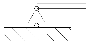
1.10.1 ROLLER (SLIDING)
The roller, or sliding constraint allows the constrained point to move freely in a plane but restricts the movement perpendicular to that plane. This kind of constraint allows rotations in every direction. Thus, the reaction force can be only perpendicular to the given plane, and the reaction moment is zero.
One unknown variable: the magnitude of the reaction force
Symbol:
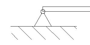
1.10.2 FLAT JOINT (HINGED, PINNED)
The flat joint or hinged (pinned) constraint allows rotations in every direction but restricts every translation. Thus, the reaction force can act in any direction, but the reaction moment is zero.
Two unknown variables: the magnitude and direction of the reaction force
Symbol:
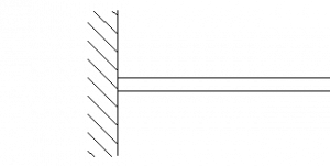
1.10.3 CANTILEVER (FIXED)
The cantilever or fixed constraint restricts every rotation and translation in every direction. Thus, the reaction force can act in any direction, and the reaction moment is not zero.
Three unknown variables: the magnitude and direction of the reaction force and the reaction moment.
Symbol:
1.10.4 A BEAM LOADED ONLY AT ITS ENDS
If the beam’s mass is neglected and is only loaded by forces at its ends, then the line of action of the force in the beam is always in line with the beam.
One unknown variable: the magnitude of the normal force in the beam
Symbol:
![]()
Trusses are built up of beams loaded only at its ends – or at least they are like that in an idealized model. The simplification that this kind of modelling gives, makes the calculation simpler by far, but only gives negligible errors in the calculated values.
1.10.5 ROPE
Similar to the beam loaded only at its ends, the force in a rope is always in line with the rope, or if the rope is curved, the acting line of the force in the rope is always tangent to the rope at the given point.
Differently from the beam, the force in a rope is always pulling, the rope is always in tension, compression is not possible.
One unknown variable: the magnitude of the pulling force in the rope.
Symbol:
![]()
1.11 INTERNAL FORCE SYSTEM OF RIGID BODIES
As previously discussed, the external forces acting on a system are the constraint (reaction) forces at the supports and constraints, and the loading (active) forces.
The external load forces exerted at one point of the structure has to “travel” somehow to the supports – that is the purpose of the structure or part in the first place. This “travel” of force means that in every cross-section of the part, an internal force system acts – burdening the structure with a certain intensity.
This internal, force intensity vector is also called “stress”. In this textbook, stresses are not discussed, but later, when studying the mechanics of solid bodies, stresses will be very important.
The load of a cross-section is defined by the reduction of the force system on one side of the cross-section to its centroid.
There are different types of internal forces depending on the types of loads.
1.11.1 NORMAL LOAD
Normal load is when the force vector is perpendicular to the inspected cross-section. It can be tension (positive) or compression (negative).
1.11.2 SHEAR LOAD
Shearing load is when the force vector is parallel with the inspected cross-section – thus perpendicular to the normal load.
1.11.3 TORSION
Torsion load is when the moment vector is perpendicular to the inspected cross-section.
1.11.4 BENDING
Bending load is when the moment vector is parallel with the inspected cross-section – thus perpendicular to the torsion moment vector.
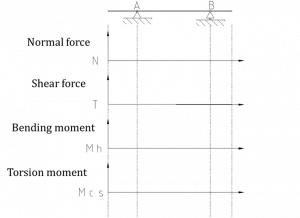
1.12 LOAD, SHEAR, AND MOMENT DIAGRAMS
Basic loads can be plotted along the beam like this:
Relation between load and internal forces:
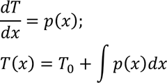
Where T0 is the initial value of shear force at x=0.
The internal shear force diagram therefore is the integral of the shear load diagram.
Respectively, the relation between the bending moment and shear force diagrams:
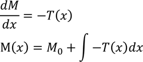
Where M0 is the initial value of bending moment at x=0.
Thus, the bending moment diagram is the integral of the shear force diagram.